Description
Sets the extra parameter needed for the digital output's calculations.
-
-
AKD-C and AKD-N only support DOUT1.
Range
DOUTx.PARAM is used for various Digital Output modes. This causes the parameter’s range to change based on the current Digital Output mode selected with the corresponding DOUTx.MODE.
Below is a list of the possible range for each Digital Output Mode.
If an output mode is not listed, then the default range of 0 is used.
| Input Mode | Min | Max | Notes |
|---|---|---|---|
| 3 | Position Min | Position Max | This value changes based on user selected position units. |
| 4 | Position Min | Position Max | This value changes based on user selected position units. |
| 5 | Position Min | Position Max | This value changes based on user selected position units. |
| 6 | Position Min | Position Max | This value changes based on user selected position units. |
| 12 | 0 | Velocity Max | This value changes based on user selected velocity units. |
| 13 | 0 | Velocity Max | This value changes based on user selected velocity units. |
| 15 | 0 | 255 | None. |
| 17 | Position Min | Position Max | This value changes based on user selected position units. |
| 23 | 0 | 1 | Selects the compare engine 0 (CMP0) or 1 (CMP1). |
| 27 | 100 | 999 | Only existing warning numbers can be used. |
Dependency on DOUTx.MODE
Since the default range of DOUTx.PARAM does not allow a user to enter a value, DOUTx.MODE must be set to a mode which uses DOUTx.PARAM before a value can be set.
Each time DOUTx.MODE is changed, DOUTx.PARAM is automatically set to zero to prevent unintended interactions.
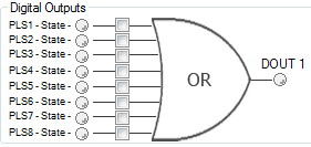
Digital Output Mode 15: PLS.STATE bits OR connected
The output mode produces a high signal if at least one of the PLS.STATE bits is high (the PLS is active) and if the corresponding bit in the DOUTx.PARAM parameter also has been set to high. The DOUTx.PARAM command connects the PLS.STATE bits to the digital output itself and thus acts as an enable mask.
In mode 15 DOUTx.PARAM is set from the Digital Outputs section of the Programmable Limit Switches screen.
This mode is valid for all opmodes and command source combinations.
Example
|<- Bit 7 to 0 ->|
DOUT1.PARAM = 23 = 0b 0 0 0 1 0 1 1 1 (Binary code)
The digital output 1 is active when bit 0 or bit 1 or bit 2 or bit 4 of PLS.STATE is high. All other bits within PLS.STATE are not considered by the digital output mode due to the DOUT1.PARAM setting. Do not use decimal places for the DOUTx.PARAM parameter for this particular digital output mode.
General Information
|
Type |
NV Parameter |
|
Units |
N/A |
|
Range |
0 Note: Range changes based on Digital Output Mode. See description above. |
|
Default Value |
0 |
|
Data Type |
Integer |
|
Start Version |
M_01-00-00-000 |
Variants Supported
| Variant | Supported |
|---|---|
| AKD Base | Yes |
| AKD with Position Indexer | Yes |
| AKD EtherCAT | Yes |
| AKD CANopen | Yes |
| AKD BASIC | Yes |
| AKD SynqNet | Yes* |
| AKD EtherNet/IP | Yes |
| AKD PROFINET | Yes |
| AKD Sercos® III | Yes |
| AKD-N | Yes |
| AKD-C | No |
*In SynqNet, a parameter may be available in the firmware but have no effect on the system. See SynqNet Supported Parameters.
Fieldbus Information
If your drive type is listed as supported but no index, address, or instance number is listed, then this parameter is accessible through WorkBench, but not over your fieldbus type.
| Index/Subindex | Object Start Version | |
|---|---|---|
|
3475h/1 (low), 3475h/3 (high) |
DOUT1.PARAM |
M_01-04-02-000 |
|
3475h/2 (low), 3475h/4 (high) |
DOUT2.PARAM |
|
| Parameter | Fieldbus | Address | Attributes | Signed? |
|---|---|---|---|---|
| DOUT1.PARAM |
PROFINET |
2099 | DWord | Yes |
| Sercos® III | 8 Octets | |||
| DOUT2.PARAM |
PROFINET |
2104 | DWord | |
| Sercos® III | 8 Octets |
| Parameter | Instance | Data Size | Data Type |
|---|---|---|---|
| DOUT1.PARAM | 100 | 8 Byte Signed | Float |
| DOUT2.PARAM | 105 |
| Parameter | Register Address | Is 64 bit? | Attributes | Signed? | Object Start Version |
|---|---|---|---|---|---|
| DOUT1.PARAM |
198 |
Yes | 64 bit | Yes | M_01-03-00-000 |
| DOUT2.PARAM | 208 |